Ciao a tutti
è forse ora di cominciare a parlare di progetti.
A parte i primi esercizietti che ci sono sul tutorial di Arduino questo è il primo progetto su cui mi sto cimentando.
Vorrei tanto controllare dei servomotori con il nunchuck della Wii.

Questo aggeggino che costa circa una decina di euro (originale) nei supermercati, è in realtà un gioiellino, infatti contiene al suo interno
- un accelerometro x, y, z (con accelerazione codificata a 10 bit),
- un joystick, la cui posizione x, y è codificata a 8 bit
- e ben due tasti (detti C e Z)
Potete perciò già immaginare quanta roba si potrebbe comandare con un solo controller.
Su ebay ho comprato e finalmente mi è arrivato un aggeggino che non fa altro che mettere il pinout del nunchuck in formato “breadboard”, fatto più o meno come nella foto seguente.

Come vedete ci sono 4 piedini:
- “-” che è l’alimentazione negativa, che va collegata a terra (GND)
- “+” che è l’alimentazione positiva che va collegata all’uscita 3.3V di Arduino
- “d” che è la porta dati
- “c” che è la porta clock
All’interno del nunchuck della Wii si entra come in un qualunque sistema I2C, cioè interrogando delle locazioni di memoria specifiche. Se volete sapere di più circa quali queste siano, quali siano le operazioni di inizializzazione e qualche dettaglio su I2C potete dare un’occhiata a questo link: http://web.engr.oregonstate.edu/~sullivae/ece375/pdf/nunchuk.pdf.
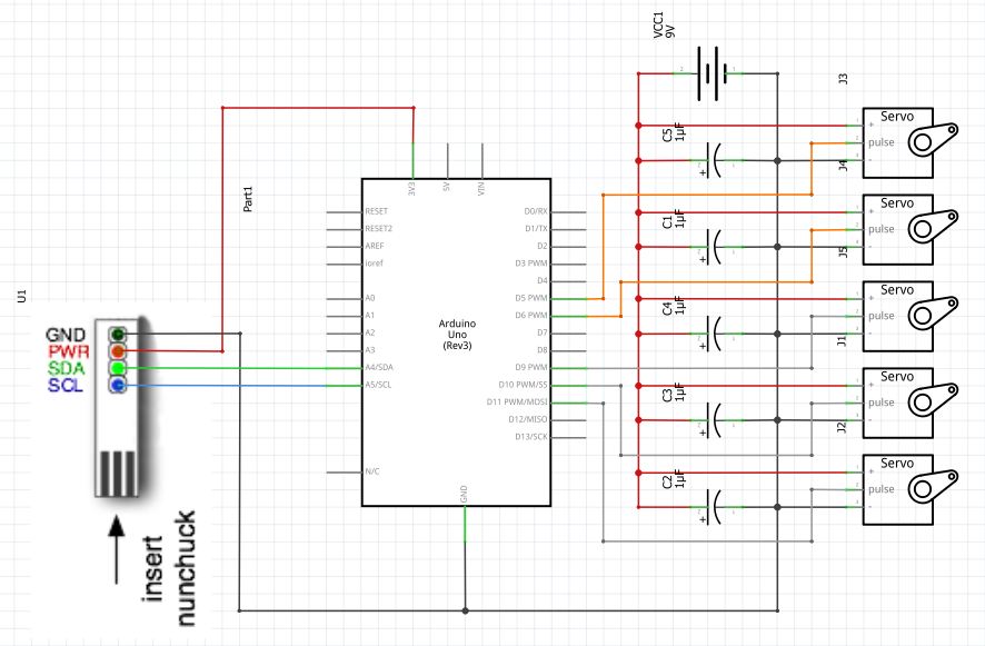
Detto questo si capisce come il circuito che c’è da costruire sia molto semplice.
Il circuito che ho disegnato per comandare 5 motori utilizzando le tre direzioni dell’accelerometro e la posizione del joystick è mostrato nelle figure seguenti.
Non sono sicuro se i condensatori ci vadano o no in realtà, ma soprattutto se invece di metterne cinque in parallelo non ne basti uno solo.
 .
.
Il listato invece si può trovare alla fine dell’articolo.
Nel codice ho fatto uso della libreria Wire.h e della libreria Servo.h.
Le librerie chiaramente sono dedicate alla gestione di interfacce I2C (la prima) e dei servomotori (la seconda).
In ogni caso quello che c’è nel video è quello che succede…
Ed infine ecco il codice.
#include <Wire.h>
#include <string.h>
#include <stdio.h>
#include <Servo.h>

// initialize the servos
Servo acc_X_Servo;
Servo acc_Y_Servo;
Servo acc_Z_Servo;
Servo joy_X_Servo;
Servo joy_Y_Servo;

// initialize constants for the servo
int angle_acc_X;
int angle_acc_Y;
int angle_acc_Z;
int angle_joy_X;
int angle_joy_Y;

uint8_t outbuf[6];

// initialize the variables
int cnt = 0; // counter

int pulseWidth = 0;
int pulseWidth2 = 0;

long lastPulse = 0;
long lastPulse2 = 0;

int z_button = 0;
int c_button = 0;

int refreshTime = 20;

int minPulse = 1000;
int minPulse2 = 500;

int dtime=50; // delay time

#define pwbuffsize 10
long pwbuff[pwbuffsize];
long pwbuffpos = 0;
long pwbuff2[pwbuffsize];
long pwbuffpos2 = 0;

void setup()
{
 // attach the servo
 acc_X_Servo.attach(9);
 acc_Y_Servo.attach(10);
 acc_Z_Servo.attach(11);
 joy_X_Servo.attach(5);
 joy_Y_Servo.attach(6);

 // init serial port
 Serial.begin(9600);

 // init nunChuck
 Wire.begin ();
 nunchuck_init ();

 Serial.print ("Finished setup\n");
 delay(dtime);
}

void nunchuck_init()
{
 Wire.beginTransmission (0x52);
 Wire.write (0x40);
 Wire.write (0x00);
 Wire.endTransmission ();
}

void send_zero()
{
 Wire.beginTransmission (0x52);
 Wire.write (0x00);
 Wire.endTransmission ();
}

int t = 0;

void loop()
{
 // increase cycle number
 t++;

 // store actual time (ms)
 long last = millis();

 if ( t == 1 ) { // odd cycle number
 // set up an even cycle
 t = 0;

 // read 6 bytes from bus at location 0x52
 Wire.requestFrom (0x52, 6);

 while ( Wire.available () ) {
 // while there are bytes available
 // the decode function is called with the bytes returned
 // by the NunChuck
 outbuf[cnt] = nunchuk_decode_byte ( Wire.read () );

 // increase the counter
 cnt++;
 }

 if (cnt >= 5) {
 // if we read more than 5 bytes init z buttons to 0
 int z_button = 0;
 int c_button = 0;

 // z and c button on the nunChuck are stored
 // in the 6th byte at bits 0 and 1.
 // The next four lines read z and c buttons values
 if ((outbuf[5] >> 0) & 1)
 z_button = 1;
 if ((outbuf[5] >> 1) & 1)
 c_button = 1;
 }

 // reset byte counter to zero
 cnt = 0;
 send_zero();
 }

 setServoAngle();
 delay(dtime);
}
// Nunchuck I2C interface bytes meaning
//Byte 0x00 : X-axis data of the joystick
//Byte 0x01 : Y-axis data of the joystick
//Byte 0x02 : X-axis data of the accellerometer sensor
//Byte 0x03 : Y-axis data of the accellerometer sensor
//Byte 0x04 : Z-axis data of the accellerometer sensor
//Byte 0x05 : bit 0 as Z button status - 0 = pressed and 1 = release
//bit 1 as C button status - 0 = pressed and 1 = release
//bit 2 and 3 as 2 lower bit of X-axis data of the accellerometer sensor
//bit 4 and 5 as 2 lower bit of Y-axis data of the accellerometer sensor
//bit 6 and 7 as 2 lower bit of Z-axis data of the accellerometer sensor
void setServoAngle()
{
 int joy_X_axis = outbuf[0]; // byte 0
 int joy_Y_axis = outbuf[1]; // byte 1
 int acc_X_axis = outbuf[2]*4; // byte 2
 int acc_Y_axis = outbuf[3]*4; // byte 3
 int acc_Z_axis = outbuf[4]*4; // byte 4

 int z_button = 0;
 int c_button = 0;

 if ((outbuf[5] >> 0) & 1) // byte 5, bit 0
 z_button = 1; // z button status
 if ((outbuf[5] >> 1) & 1) // byte 5, bit 1
 c_button = 1; // c button status
 if ((outbuf[5] >> 2) & 1) // byte 5, bit 2
 acc_X_axis += 2; // additional +2 accel X axis
 if ((outbuf[5] >> 3) & 1) // byte 5, bit 3
 acc_X_axis += 1; // additional +1 accel X axis

 if ((outbuf[5] >> 4) & 1) // byte 5, bit 4
 acc_Y_axis += 2; // additional`+2 accel Y axis
 if ((outbuf[5] >> 5) & 1) // byte 5, bit 5
 acc_Y_axis += 1; // additional +1 accel Y axis

 if ((outbuf[5] >> 6) & 1) // byte 5, bit 6
 acc_Z_axis += 2; // additional +2 accel Z axis
 if ((outbuf[5] >> 7) & 1) // byte 5, bit 7
 acc_Z_axis += 1; // additional +1 accel Z axis

 // calc angles
 angle_acc_X = map ( acc_X_axis, 0, 1023, 0, 179 );
 angle_acc_Y = map ( acc_Y_axis, 0, 1023, 0, 179 );
 angle_acc_Z = map ( acc_Z_axis, 0, 1023, 0, 179 );
 angle_joy_X = map ( joy_X_axis, 0, 255, 0, 179 );
 angle_joy_Y = map ( joy_Y_axis, 0, 255, 0, 179 );

 // write to servo
 acc_X_Servo.write ( angle_acc_X );
 acc_Y_Servo.write ( angle_acc_Y );
 acc_Z_Servo.write ( angle_acc_Z );
 joy_X_Servo.write ( angle_joy_X );
 joy_Y_Servo.write ( angle_joy_Y );


 nunChuckPrint(acc_X_axis, acc_Y_axis, acc_Z_axis, joy_X_axis, joy_Y_axis );
}

void nunChuckPrint(int acc_X_axis, int acc_Y_axis, int acc_Z_axis, int joy_X_axis, int joy_Y_axis){
 Serial.print ("AccX: ");
 Serial.print (acc_X_axis, DEC);
 Serial.print (" (");
 Serial.print (angle_acc_X, DEC);
 Serial.print (")\t");

 Serial.print ("AccY: ");
 Serial.print (acc_Y_axis, DEC);
 Serial.print (" (");
 Serial.print (angle_acc_X, DEC);
 Serial.print (")\t");

 Serial.print ("AccZ: ");
 Serial.print (acc_Z_axis, DEC);
 Serial.print (" (");
 Serial.print (angle_acc_X, DEC);
 Serial.print (")\t");

 Serial.print ("JoyX: ");
 Serial.print (joy_X_axis, DEC);
 Serial.print (" (");
 Serial.print (angle_joy_X, DEC);
 Serial.print (")\t");

 Serial.print ("JoyY: ");
 Serial.print (joy_Y_axis, DEC);
 Serial.print (" (");
 Serial.print (angle_joy_Y, DEC);
 Serial.print (")\n");
}

char nunchuk_decode_byte ( char x ) {
 // devo capirlo meglio ma ^ è un XOR bit a bit
 x = (x ^ 0x17) + 0x17;
 return x;
}

dove trovi le librerie?? Io non le trovo da nessuna parte!!
"Mi piace""Mi piace"
Ciao Mattia.
Le librerie, in particolare quelle che uso per questo progetto, sono incluse nell’IDE di Arduino.
Tutte le informazioni sulla libreria Wire possono essersi trovate al link http://www.arduino.cc/en/Reference/Wire
Invece la libreria Servo può essere studiata al link http://www.arduino.cc/en/Reference/Servo
"Mi piace""Mi piace"
ma…le librerie stdio.h e string.h dove le hai trovate?
"Mi piace""Mi piace"