
Ciao a tutti
Sono andato avanti con il progettino del rover a due ruote motrici di cui avevo già parlato, rendendolo wireless.
Per farlo ho usato due schedine molto interessanti che contengono un altrettanto interessante integrato della Nordic RF, nRF2401L (le specifiche potete trovarle sul sito della Nordic Semiconductors). Le caratteristiche più interessanti di questo integrato sono descritte nelle prime righe della pagina della Nordic:
si tratta di un integrato ricetrasmittente altamente integrato, a potenza estremamente bassa (ultra low power) da 2 Mbps, per la banda 2.4Ghz (industriale, scientifica, medicale). Con correnti di picco RX/RT minori di 14 mA, una modalità di risparmio con consumi sotto il μA, gestione energetica avanzata, e una tensione di funzionamento 1.9-3.6 V, il nRF24L01 fornisce una soluzione davvero ULP (ultra low power), dando al circuito la possibilità di funzionare per mesi o anni solo con batterie a bottone o stilo/ministilo.
come potete immaginare, un circuito di questo tipo su un rover o un apparecchio autonomo è altamente desiderabile.
La versione che ho comprato viene dalla Cina attraverso eBay ed è fatto più o meno come in figura.

Una cosa un po’ fastidiosa di questo piccolo shield sono i piedini, disposti su una doppia fila, che non lo rendono adatto ad una breadboard, ma che in realtà sono ottimi per inserirlo in un circuito stampato ad hoc. La piedinatura è visibile nella immagine successiva.

Ho dovuto usare due di queste schedine, configurate come trasmittente (sul telecomando) e ricevente (sul roverino).
Altre modifiche che ho fatto riguardano il codice relativo alla conversione dei comandi che arrivano dal Nunchuck in impulsi per il ponte di diodi L293D, in maniera da rendere più fluido il movimento del roverino.
Il telecomando
Per il telecomando ho usato:
- 1 Arduino Nano
- 1 Interfaccia Nunchuck
- 1 Nunchuck Wii
- 1 display OLED 0.96″ bicolore
- 1 nRF 24L01
Come potete vedere non ci sono grosse differenze rispetto al progetto precedente. Ho deciso di spostare il display OLED su questo progetto al telecomando per avere una visione immediata di quello che viene letto dal Nunchuck, ma nulla vieta in future implementazioni che sul display possano apparire informazioni trasmesse dal rover. Questo è possibile perchè il nRf24L01 trasmette in maniera bidirezionale e quindi la parte circuitale potrebbe rimanere la stessa, cambiando solo il software.
Il rover
Per il rover invece ho usato:
- 1 Arduino UNO
- 1 nRF 24L01
- il telaio già utilizzato per il precedente progetto
In un certo senso quindi l’hardware del rover in sè si è semplificato.
Il Nunchuck e il bus I2C
Per delucidazioni sul Nunchuck e sul bus I2C fate riferimento a questo articolo.
Il chip L293D e i due motori
Per il chip L293D fate riferimento a questo articolo.
Il display OLED
Per quanto riguarda il display OLED fate riferimento a questo articolo.
Gli schemi elettrici
Gli schemi elettrici sono molto semplici e pertanto vi posto solo i diagrammi Fritzing.
A questo proposito ho creato una parte fritzing per l’adattatore del Nunchuck, per il display OLED e per il modulo nRF24L01, se vi servisse posso inviarla via mail, dato che wordpress non mi lascia caricare i file fzpz.
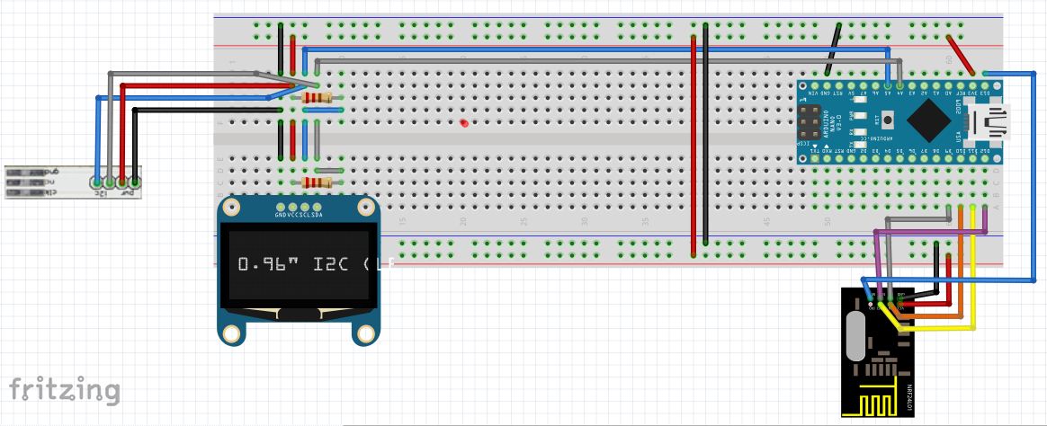
Lo schema elettrico del telecomando
Di seguito riporto lo schema del telecomando se per caso voleste cimentarvi nel costruirlo.
Lo schema elettrico del rover
Di seguito riporto lo schema del roverino se per caso voleste cimentarvi nel costruirlo.

Analisi del Codice
Il codice per il telecomando
Dichiarazioni
Nella parte dichiarativa, importiamo tutte le librerie necessarie al funzionamento del codice.
#include <U8glib.h>
#include <Wire.h>
#include <SPI.h>
#include "printf.h"
#include "NRF24L01.h"
Ho bisogno poi di definire quanti byte è lungo l’indirizzo a cui trasmettere (TX_ADR_WIDTH) e quanti byte leggere per ogni ciclo di trasmissione/ricezione (payload = TX_PLOAD_WIDTH). In questo caso verranno trasmessi 6 byte (payload), che corrisponderanno esattamente ai byte contenuti nei registri del Nunchuck.
// Radio configuration
#define TX_ADR_WIDTH 5   //  5 unsigned chars TX(RX) address width
#define TX_PLOAD_WIDTH 6 // 32 unsigned chars TX payload
Quindi, inizializzo alcune variabili che verranno usate per pilotare il display OLED e per leggere il contenuto dei registri all’interno del Nunchuck.
Setup
Come prima cosa inizializziamo le librerie legate al nRF24L01. In particolare impostiamo i pin secondo la funzione che svolgeranno all’interno della libreria SPI.
 pinMode(nRF24L01_CE, OUTPUT);
 pinMode(nRF24L01_SCK, OUTPUT);
 pinMode(nRF24L01_CSN, OUTPUT);
 pinMode(nRF24L01_MOSI, OUTPUT);
 pinMode(nRF24L01_MISO, INPUT);
 pinMode(nRF24L01_IRQ, INPUT);
Posso quindi inizializzare la porta seriale e chiamare la funzione init_io()
 Serial.begin(9600);
 init_io(); // Initialize IO port
La funzione init_io() non fa altro che scrivere zero sulla porta IRQ, effettuare un CE (chip enable) e disabilitare la SPI, ponendo la linea di clock ad uno stato alto.
//**************************************************
// Function: init_io();
// Description:
// flash led one time,chip enable(ready to TX or RX Mode),
// Spi disable, Spi clock line init high
//**************************************************
void init_io(void)
{
 digitalWrite(nRF24L01_IRQ, 0);
 digitalWrite(nRF24L01_CE, 0); // chip enable
 digitalWrite(nRF24L01_CSN, 1); // Spi disable
}
A questo punto posso chiamare la funzione SPI_Read per il registro STATUS, e scriverne il risultato sulla seriale, utilizzato come debug.
Posso poi anche far partire la modalità di trasmissione:
 unsigned char status=SPI_Read(STATUS);
 Serial.print("status = ");
 Serial.println(status,HEX); // There is read the mode’s status register, the default value should be ‘E’
 Serial.println("----- TX_Mode Start ---");
 TX_Mode(); // set TX mode
La funzione SPI_Read non fa altro che restituire un valore unsigned char dal registro che si passa come argomento.
La funzione TX_Mode, invece, inizializza un dispositivo nRF24L01 device al modo TX (trasmissione, imposta l’indirizzo TX, imposta l’indirizzo RX address per l’auto.ack, riempie il payload TX, seleziona il canale RF, la velocità e la potenza di trasmissione. Si impostano inoltre PWR_UP, si abilita il CRC (2 unsigned chars) e il PRIM:TX.
Il resto della funzione di setup è dedicato alla inizializzazione del display OLED e del Nunchuck, di cui abbiamo già parlato in altri articoli.
Loop
Nella prima parte si leggono i registri del Nunchuck (sei byte, che vengono immagazzinati in output_buf[], quindi si passa alla parte relativa al nRF24L01.
Innanzitutto si legge il registro di stato, tramite il solito comando SPI_Read.
unsigned char status = SPI_Read(STATUS); // read register STATUS's value
Se il dispositivo è pronto a trasmettere, si fa il flush del registro e si scrive il contenuto della variabile output_buf (cioè il contenuto dei registri del Nunchuk che abbiamo appena letto) alla coda trasmissiva (TX_FIFO)
 if(status&TX_DS) // if receive data ready (TX_DS) interrupt
 {
 SPI_RW_Reg(FLUSH_TX,0);
 SPI_Write_Buf(WR_TX_PLOAD,outbuf,TX_PLOAD_WIDTH); // write playload to TX_FIFO
 }
Se il dispositivo si trova in uno stato di ricezione, siamo in una condizione di ritrasmissione, per cui riproviamo a trasmettere per una volta.
  if(status&MAX_RT) // if receive data ready (MAX_RT) interrupt, this is retransmit than SETUP_RETR
 {
 SPI_RW_Reg(FLUSH_TX,0);
 SPI_Write_Buf(WR_TX_PLOAD,outbuf,TX_PLOAD_WIDTH); // disable standby-mode
 }
a questo punto i registri del dispositivo possono essere ripuliti dai rispettivi flag di interrupt.
SPI_RW_Reg(WRITE_REG+STATUS,status); // clear RX_DR or TX_DS or MAX_RT interrupt flag
Di seguito il codice chiama la funzione di decodifica del contenuto del Nunchuck e la funzione di disegno su OLED, che serviranno come debug visivo del sistema, per capire quali siano i valori presenti all’interno del nunchuck, in maniera grafica.
Il codice per il rover
Dichiarazioni
Innanzitutto si includono le librerie necessarie al funzionamento del codice.
// include the library code:
#include <SPI.h>
#include "NRF24L01.h"
#include "printf.h"
#include <math.h>
Dopo una piccola parte relativa alla inizializzazione di alcuni parametri relativi al movimento e alla connessione delle porte di arduino al chip L293D, si definisce l’interfaccia radio e le sue costanti. In particolare si definiscono la lunghezza dell’indirizzo ed il payload trasmissivo esattamente come per il telecomando.
// Radio configuration
#define TX_ADR_WIDTH 5 // 5 unsigned chars TX(RX) address width
#define TX_PLOAD_WIDTH 6 // 32 unsigned chars TX payload

unsigned char TX_ADDRESS[TX_ADR_WIDTH] =
{
 0x34,0x43,0x10,0x10,0x01
}; // Define a static TX address

unsigned char rx_buf[TX_PLOAD_WIDTH];
unsigned char tx_buf[TX_PLOAD_WIDTH];
Si passa quindi a definire una serie di parametri che saranno utili per decodificare i comandi in arrivo dal Nunchuck sul telecomando per poterli trasformare in comandi per i motori.
Setup
Si inizializzano innanzitutto i pin di Arduino destinati alla comunicazione con il nRF24L01.
 pinMode(nRF24L01_CE, OUTPUT);
 pinMode(nRF24L01_SCK, OUTPUT);
 pinMode(nRF24L01_CSN, OUTPUT);
 pinMode(nRF24L01_MOSI, OUTPUT);
 pinMode(nRF24L01_MISO, INPUT);
 pinMode(nRF24L01_IRQ, INPUT);
Il resto della inizializzazione ricalca quella che è stata fatta per il telecomando eccetto quanto riguarda l’inizializzazione finale, qui fatta attraverso la funzione RX_Mode().
 Serial.begin(9600);
 init_io(); // Initialize IO port
 unsigned char status=SPI_Read(STATUS);
 Serial.print("status = ");
 Serial.println(status,HEX); // There is read the mode’s status register, the default value should be ‘E’
 Serial.println("----- RX_Mode start -----");
 RX_Mode(); // set RX mode
La funzione RX_Mode() inizializza un dispositivo nRF24L01 al modo di ricezione (RX Mode), imposta l’indirizzo RX, scrive la dimensione del payload RX, selezionail canale RF, il datarate e LNA HCURR. Dopo l’inizializzazione, CE è in stato ALTO, il che significa che il dispositivo è pronto a ricevere un pacchetto dati.
La parte restante del codice di setup si occupa di inizializzare i piedini associati al chip L293D
 pinMode(en1Pin, OUTPUT);
 pinMode(in1Pin, OUTPUT);
 pinMode(in2Pin, OUTPUT);
 pinMode(en2Pin, OUTPUT);
 pinMode(in3Pin, OUTPUT);
 pinMode(in4Pin, OUTPUT);
Loop
Come sempre la prima cosa da fare è leggere il registro di stato del nRF24L01.
unsigned char status = SPI_Read(STATUS); // read register STATUS's value
se il dispositivo è pronto a ricevere dati, leggiamo il contenuto del payload e lo scriviamo dentro la variabile rx_buf, che si comporterà esattamente come la variabile output_buf del telecomando, contenendo in tal modo i valori dei registri del Nunchuck, trasmessi dal telecomando (si spera!) :). A questo punto si può ripulire la coda FIFO RX. Il for successivo è dedicato al debug. A questo punto si potrà decodificare e stampare sulla seriale i dati del Nunchuck
 if(status&RX_DR) // if receive data ready (RX_DR) interrupt
 {
 SPI_Read_Buf(RD_RX_PLOAD, rx_buf, TX_PLOAD_WIDTH); // read payload to rx_buf
 SPI_RW_Reg(FLUSH_RX,0); // clear RX_FIFO
 for(int i=0; i<TX_PLOAD_WIDTH; i++)
 {
 Serial.print("|");
 Serial.print(rx_buf[i],HEX); // print rx_buf
 }
 Serial.print("|\t ");
 decodeNunchuckData();
 printNunchuckData();
 }
A questo punto si posso ripulire i flag di interrupt di RX_DR, TX_DS e MAX_RT.
SPI_RW_Reg(WRITE_REG+STATUS,status); // clear RX_DR or TX_DS or MAX_RT interrupt flag
Di conseguenza si possono inviare i dati ai motori per poter far muovere il rover.
runMyCar();
Codici Completi
Codici aggiuntivi
Per il funzionamento del codice sia del telecomando, sia del rover c’è bisogno di aggiungere dei codici aggiuntivi, per mezzo dell’inserimento di nuovi “tab”.
I codici aggiuntivi sono riportati di seguito.
Il codice aggiuntivo printf.h
Questo codice aggiuntivo è necessario per redirigere l’output standard (stdout) alla libreria Serial di Arduino, abilitando così la funzione printf.
/*
 Copyright (C) 2011 J. Coliz <maniacbug@ymail.com>

 This program is free software; you can redistribute it and/or
 modify it under the terms of the GNU General Public License
 version 2 as published by the Free Software Foundation.
 */

/**
 * @file printf.h
 *
 * Setup necessary to direct stdout to the Arduino Serial library, which
 * enables 'printf'
 */

#ifndef __PRINTF_H__
#define __PRINTF_H__

#ifdef ARDUINO

int serial_putc( char c, FILE * )
{
 Serial.write( c );

 return c;
}

void printf_begin(void)
{
 fdevopen( &serial_putc, 0 );
}

#else
#error This example is only for use on Arduino.
#endif // ARDUINO

#endif // __PRINTF_H__
Il codice aggiuntivo NRF24L01.h
Questo codice aggiuntivo contiene una serie di costanti utili per il funzionamento del modulo nRF24L01.
#ifndef NRF24L01_h
#define NRF24L01_h

//---------------------------------------------
#define TX_ADR_WIDTH 5
// 5 unsigned chars TX(RX) address width
#define TX_PLOAD_WIDTH 1
// 1 unsigned chars TX payload
//---------------------------------------------
#define nRF24L01_CE 8
// CE_BIT: Digital Input Chip Enable Activates RX or TX mode
#define nRF24L01_CSN 9
// CSN BIT: Digital Input SPI Chip Select
#define nRF24L01_SCK 10
// SCK BIT: Digital Input SPI Clock
#define nRF24L01_MOSI 11
// MOSI BIT: Digital Input SPI Slave Data Input
#define nRF24L01_MISO 12
// MISO BIT: Digital Output SPI Slave Data Output, with tri-state option
#define nRF24L01_IRQ 13
// IRQ BIT: Digital Output Maskable interrupt pin
//*********************************************
// SPI(nRF24L01) commands
#define READ_REG 0x00 // Define read command to register
#define WRITE_REG 0x20 // Define write command to register
#define RD_RX_PLOAD 0x61 // Define RX payload register address
#define WR_TX_PLOAD 0xA0 // Define TX payload register address
#define FLUSH_TX 0xE1 // Define flush TX register command
#define FLUSH_RX 0xE2 // Define flush RX register command
#define REUSE_TX_PL 0xE3 // Define reuse TX payload register command
#define NOP 0xFF // Define No Operation, might be used to read status register
//***************************************************
#define RX_DR 0x40
#define TX_DS 0x20
#define MAX_RT 0x10
//***************************************************
// SPI(nRF24L01) registers(addresses)
#define CONFIG 0x00 // 'Config' register address
#define EN_AA 0x01 // 'Enable Auto Acknowledgment' register address
#define EN_RXADDR 0x02 // 'Enabled RX addresses' register address
#define SETUP_AW 0x03 // 'Setup address width' register address
#define SETUP_RETR 0x04 // 'Setup Auto. Retrans' register address
#define RF_CH 0x05 // 'RF channel' register address
#define RF_SETUP 0x06 // 'RF setup' register address
#define STATUS 0x07 // 'Status' register address
#define OBSERVE_TX 0x08 // 'Observe TX' register address
#define CD 0x09 // 'Carrier Detect' register address
#define RX_ADDR_P0 0x0A // 'RX address pipe0' register address
#define RX_ADDR_P1 0x0B // 'RX address pipe1' register address
#define RX_ADDR_P2 0x0C // 'RX address pipe2' register address
#define RX_ADDR_P3 0x0D // 'RX address pipe3' register address
#define RX_ADDR_P4 0x0E // 'RX address pipe4' register address
#define RX_ADDR_P5 0x0F // 'RX address pipe5' register address
#define TX_ADDR 0x10 // 'TX address' register address
#define RX_PW_P0 0x11 // 'RX payload width, pipe0' register address
#define RX_PW_P1 0x12 // 'RX payload width, pipe1' register address
#define RX_PW_P2 0x13 // 'RX payload width, pipe2' register address
#define RX_PW_P3 0x14 // 'RX payload width, pipe3' register address
#define RX_PW_P4 0x15 // 'RX payload width, pipe4' register address
#define RX_PW_P5 0x16 // 'RX payload width, pipe5' register address
#define FIFO_STATUS 0x17 // 'FIFO Status Register' register address

#endif
Telecomando
Di seguito incollo il codice che ho scritto per il funzionamento del telecomando.
/*
 Copyright (C) 2014 P. Luisi <pierluigi.luisi@gmail.com>

 This program is free software; you can redistribute it and/or
 modify it under the terms of the GNU General Public License
 version 2 as published by the Free Software Foundation.

This code is based on the following code:
- test code for the http://code.google.com/p/u8glib/ library
- http://learn.linksprite.com/pcduino/arduino-ish-program/spi/nrf24l01-for-pcduino/
*/

// include the library code:
#include <U8glib.h>
#include <Wire.h>
#include <SPI.h>
#include "printf.h"
#include "NRF24L01.h"


/***************************************************
Radio configuration and connections for nRF24L01
*****************************************************
 GND ------ GND -| |- VCC ------ 3.3V
 D08 ------- CE -| |- CSN ------ D09
 D10 ------ SCK -| |- MOSI ----- D11
 D12 ----- MISO -| |- IRQ ------ D13
*/
// Radio configuration
#define TX_ADR_WIDTH 5   //  5 unsigned chars TX(RX) address width
#define TX_PLOAD_WIDTH 6 // 32 unsigned chars TX payload

// Define a static TX address
unsigned char TX_ADDRESS[TX_ADR_WIDTH] =
{
 0x34,0x43,0x10,0x10,0x01
};

// Create buffers and initialize values
unsigned char rx_buf[TX_PLOAD_WIDTH] = {0};
unsigned char tx_buf[TX_PLOAD_WIDTH] = {0};
//***************************************************

/***************************************************
// OLED Configuration
*/
// initialize the OLED library with the numbers of the interface pins
U8GLIB_SSD1306_128X64 u8g(U8G_I2C_OPT_NO_ACK); // Display which does not send ACK
int disp_w = 128;
int disp_h = 64;

/***************************************************
// Nunchuck helper variables
*/
// this comes from nunchuck init
uint8_t outbuf[6];
int joy_x_axis;
int joy_y_axis;
int accel_x_axis;
int accel_y_axis;
int accel_z_axis;
int z_button = 0;
int c_button = 0;
int data[9];

int t = 0;
int i = 0;
int cnt = 0;
int dtime = 50;

/**************************************************
 * setup
 **************************************************/
void setup(){
 // ****** Radio init ******
 //
 pinMode(nRF24L01_CE, OUTPUT);
 pinMode(nRF24L01_SCK, OUTPUT);
 pinMode(nRF24L01_CSN, OUTPUT);
 pinMode(nRF24L01_MOSI, OUTPUT);
 pinMode(nRF24L01_MISO, INPUT);
 pinMode(nRF24L01_IRQ, INPUT);
 // attachInterrupt(1, _ISR, LOW);// interrupt enable
 Serial.begin(9600);
 init_io(); // Initialize IO port
 unsigned char status=SPI_Read(STATUS);
 Serial.print("status = ");
 Serial.println(status,HEX); // There is read the mode’s status register, the default value should be ‘E’
 Serial.println("----- TX_Mode Start ---");
 TX_Mode(); // set TX mode

 // ****** NUNCHUCK init ******
 //
 Wire.begin ();
 nunchuck_init ();

 // ****** U8g library init ******
 //
 u8g_prepare();
 u8g.firstPage();
 do {
 u8g.setColorIndex(1);
 u8g.drawBox(0, 0, disp_w-1, (disp_h/4)-1);
 u8g.setColorIndex(0);
 u8g.drawStr( int((disp_w - u8g.getStrWidth("Nunchuck + OLED")) / 2), 4, "Nunchuck + OLED");
 }
 while( u8g.nextPage() );

 Serial.print ("Finished setup\n");

 delay (1000);
}

/**************************************************
 * loop
 **************************************************/
void loop(){
 t++;
 long last = millis();

 if( t == 1 ) {
 t = 0;
 Wire.requestFrom (0x52, 6); // Leggo il registro del Nunchuck
 while (Wire.available ()) { // Leggo tutti i byte disponibili sul Nunchuck
 outbuf[cnt] = nunchuk_decode_byte (Wire.read ());
 cnt++;
 }
 if (cnt >= 5) {
 int z_button = 0;
 int c_button = 0;
 if ((outbuf[5] >> 0) & 1)
 z_button = 1;
 if ((outbuf[5] >> 1) & 1)
 c_button = 1;
 }
 cnt = 0;
 send_zero();
 } // endif(t==)

 unsigned char status = SPI_Read(STATUS); // read register STATUS's value
 if(status&TX_DS) // if receive data ready (TX_DS) interrupt
 {
 SPI_RW_Reg(FLUSH_TX,0);
 SPI_Write_Buf(WR_TX_PLOAD,outbuf,TX_PLOAD_WIDTH); // write playload to TX_FIFO
 }
 if(status&MAX_RT) // if receive data ready (MAX_RT) interrupt, this is retransmit than SETUP_RETR
 {
 SPI_RW_Reg(FLUSH_TX,0);
 SPI_Write_Buf(WR_TX_PLOAD,outbuf,TX_PLOAD_WIDTH); // disable standby-mode
 }
 SPI_RW_Reg(WRITE_REG+STATUS,status); // clear RX_DR or TX_DS or MAX_RT interrupt flag

 decodeNunchuckData();
 drawDataOnOLED();
 // Try again 50ms later
 delay(50);
}

/**************************************************
 * Function: decodeNunchuckData();
 *
 * Description:
 * Takes the data stored in the 6 bytes array coming from the
 * nunchuck, that has been stored in the outbuf[] array
 * and writes it to the explicit variables used throughout
 * the whole sketch.
 **************************************************/
void decodeNunchuckData() {
 joy_x_axis = outbuf[0]; // outbuf[0] contains value of the X axis of the joystick
 joy_y_axis = outbuf[1]; // outbuf[1] contains value of the Y axis of the joystick
 accel_x_axis = outbuf[2] * 2 * 2; // outbuf[2] contains 8 most significant bits of the X axis of the accelerometer
 accel_y_axis = outbuf[3] * 2 * 2; // outbuf[3] contains 8 most significant bits of the Y axis of the accelerometer
 accel_z_axis = outbuf[4] * 2 * 2; // outbuf[4] contains 8 most significant bits of the Z axis of the accelerometer

 z_button = 0;
 c_button = 0;

/*
Structure of outbuf[5]
bits, from MSB to LSB, left to right:
 7 6 5 4 3 2 1 0
 | | | | | | | └-- Z button
 | | | | | | └-- C button
 | | | | | └-- bit 1 of the X axis of the accelerometer
 | | | | └-- bit 0 of the X axis of the accelerometer
 | | | └-- bit 1 of the Y axis of the accelerometer
 | | └-- bit 0 of the Y axis of the accelerometer
 | └-- bit 1 of the Z axis of the accelerometer
 └-- bit 0 of the Z axis of the accelerometer
*/
 if ((outbuf[5] >> 0) & 1)
 z_button = 1; // bit 0 of outbuf[5] contains status of the Z button
 if ((outbuf[5] >> 1) & 1)
 c_button = 1; // bit 1 of outbuf[5] contains status of the Z button
 if ((outbuf[5] >> 2) & 1)
 accel_x_axis += 2; // bit 2 of outbuf[5] contains bit 1 of the X axis of the accelerometer
 if ((outbuf[5] >> 3) & 1)
 accel_x_axis += 1; // bit 3 of outbuf[5] contains bit 0 of the X axis of the accelerometer

 if ((outbuf[5] >> 4) & 1)
 accel_y_axis += 2; // bit 4 of outbuf[5] contains bit 1 of the Y axis of the accelerometer
 if ((outbuf[5] >> 5) & 1)
 accel_y_axis += 1; // bit 5 of outbuf[5] contains bit 0 of the Y axis of the accelerometer

 if ((outbuf[5] >> 6) & 1)
 accel_z_axis += 2; // bit 6 of outbuf[5] contains bit 1 of the Z axis of the accelerometer
 if ((outbuf[5] >> 7) & 1)
 accel_z_axis += 1; // bit 7 of outbuf[5] contains bit 0 of the Z axis of the accelerometer
}

/**************************************************
 * Function: nunchuck_init();
 *
 * Description:
 * Begins transmission with the Nunchuck at the address 0x52
 * and writes 0x40 and 0x00 to effectively start it
 **************************************************/
void nunchuck_init(){
 Wire.beginTransmission (0x52);
 Wire.write (0x40);
 Wire.write (0x00);
 Wire.endTransmission ();
}

/**************************************************
 * Function: send_zero();
 *
 * Description:
 * Begins transmission with the Nunchuck at the address 0x52
 * and writes 0x00 to it
 **************************************************/
void send_zero(){
 Wire.beginTransmission (0x52);
 Wire.write (0x00);
 Wire.endTransmission ();
}

/**************************************************
 * Function: u8g_prepare();
 *
 * Description:
 * Prepare U8G library using regular font
 **************************************************/
void u8g_prepare(void) {
 u8g.setFont(u8g_font_6x10);
 u8g.setFontRefHeightExtendedText();
 u8g.setDefaultForegroundColor();
 u8g.setFontPosTop();
}

/**************************************************
 * Function: u8g_prepare_micro();
 *
 * Description:
 * Prepare U8G library using micro font
 **************************************************/
void u8g_prepare_micro(void) {
 u8g.setFont(u8g_font_micro);
 u8g.setFontRefHeightExtendedText();
 u8g.setDefaultForegroundColor();
 u8g.setFontPosTop();
}

/**************************************************
 * Function: printDataOnSerial();
 *
 * Description:
 * write data coming from the Nunchuck to Serial interface
 **************************************************/
void printDataOnSerial() {
 Serial.print (i,DEC);
 Serial.print ("\t");

 Serial.print ("X: ");
 Serial.print (joy_x_axis, DEC);
 Serial.print ("\t");

 Serial.print ("Y: ");
 Serial.print (joy_y_axis, DEC);
 Serial.print ("\t");

 Serial.print ("AccX: ");
 Serial.print (accel_x_axis, DEC);
 Serial.print ("\t");

 Serial.print ("AccY: ");
 Serial.print (accel_y_axis, DEC);
 Serial.print ("\t");

 Serial.print ("AccZ: ");
 Serial.print (accel_z_axis, DEC);
 Serial.print ("\t");

 Serial.print (z_button, DEC);
 Serial.print (" ");
 Serial.print (c_button, DEC);
 Serial.print ("\r\n");
 i++;
}

/**************************************************
 * Function: drawDataOnOLED();
 *
 * Description:
 * draw data coming from the Nunchuck to OLED display
 **************************************************/
void drawDataOnOLED() {
 int jx = map (joy_x_axis, 0, 255, 2, (disp_w/2)-3);
 int jy = map (joy_y_axis, 0, 255, disp_h-3, (disp_h/4)+2);
 int ax = map (accel_x_axis, 0, 1023, (disp_w/2)+1, disp_w-2);
 int ay = map (accel_y_axis, 0, 1023, disp_h-3, (disp_h/4)+2);
 int az = map (accel_z_axis, 0, 1023, disp_w/4, 3*(disp_w/4));

 u8g.firstPage();
 do {
 // draw debug area
 u8g_prepare_micro();
 u8g.drawBox (0,0,10,14);
 u8g_prepare();
 u8g.setColorIndex(0);
 u8g.drawStr(2, 3, "Z");
 if(z_button) {
 u8g.drawBox(1, 1, 8, 12);
 }
 u8g.setColorIndex(1);
 u8g.drawBox (118,0,10,14);
 u8g.setColorIndex(0);
 u8g.drawStr(120, 3, "C");
 if(c_button) {
 u8g.drawBox(119, 1, 8, 12);
 }

 //draw graphic area
 u8g.setColorIndex(1);
 u8g.drawVLine(31,16,46);
 u8g.drawHLine(1,40,62);
 u8g.drawDisc(jx,jy,2);

 u8g.drawVLine(95,16,46);
 u8g.drawHLine(65,40,62);
 u8g.drawDisc(ax,ay,2);

 if (az > 63){
 u8g.drawBox(63,16,az-63,3);
 }
 else {
 u8g.drawBox(az,16,63-az,3);
 }

 }
 while( u8g.nextPage() );
 i++;
}

/**************************************************
 * Function: nunchuk_decode_byte();
 *
 * Description:
 * this function was in the Nunchuck library
 * It's not clear what it's meant for
 **************************************************/
char nunchuk_decode_byte (char x) {
 x = (x ^ 0x17) + 0x17;
 return x;
}

/**************************************************
 * Function: drawLabelInt();
 *
 * Description:
 * draws a label 'label' and an integer value 'val' to OLED
 * at the position ('x', 'y')
 **************************************************/
void drawLabelInt(int x, int y, char *label, int val) {
 u8g.drawStr (x, y, label);
 u8g.setPrintPos ( x + u8g.getStrWidth(label), y);
 u8g.print (val);
}

/**************************************************
 * Function: drawLabelUL();
 *
 * Description:
 * draws a label 'label' and an unsignel long value 'val' to OLED
 * at the position ('x', 'y')
 **************************************************/
void drawLabelUL(int x, int y, char *label, unsigned long val) {
 u8g.drawStr (x, y, label);
 u8g.setPrintPos ( x + u8g.getStrWidth(label), y);
 u8g.print (val);
}

//**************************************************
// Function: init_io();
// Description:
// flash led one time,chip enable(ready to TX or RX Mode),
// Spi disable,Spi clock line init high
//**************************************************
void init_io(void)
{
 digitalWrite(nRF24L01_IRQ, 0);
 digitalWrite(nRF24L01_CE, 0); // chip enable
 digitalWrite(nRF24L01_CSN, 1); // Spi disable
}

/**************************************************
 * Function: SPI_RW();
 *
 * Description:
 * Writes one unsigned char to nRF24L01, and return the unsigned char read
 * from nRF24L01 during write, according to SPI protocol
 **************************************************/
unsigned char SPI_RW(unsigned char Byte)
{
 unsigned char i;
 for(i=0;i<8;i++) // output 8-bit
 {
 if(Byte&0x80)
 {
 digitalWrite(nRF24L01_MOSI, 1);
 }
 else
 {
 digitalWrite(nRF24L01_MOSI, 0);
 }
 digitalWrite(nRF24L01_SCK, 1);
 Byte <<= 1; // shift next bit into MSB..
 if(digitalRead(nRF24L01_MISO) == 1)
 {
 Byte |= 1; // capture current MISO bit
 }
 digitalWrite(nRF24L01_SCK, 0);
 }
 return(Byte); // return read unsigned char
}
/**************************************************/

/**************************************************
 * Function: SPI_RW_Reg();
 *
 * Description:
 * Writes value 'value' to register 'reg'
/**************************************************/
unsigned char SPI_RW_Reg(unsigned char reg, unsigned char value)
{
 unsigned char status;

 digitalWrite(nRF24L01_CSN, 0); // CSN low, init SPI transaction
 status = SPI_RW(reg); // select register
 SPI_RW(value); // ..and write value to it..
 digitalWrite(nRF24L01_CSN, 1); // CSN high again

 return(status); // return nRF24L01 status unsigned char
}
/**************************************************/

/**************************************************
 * Function: SPI_Read(unsigned char reg);
 *
 * Description:
 * Read one unsigned char from nRF24L01 register, 'reg'
/**************************************************/
unsigned char SPI_Read(unsigned char reg)
{
 unsigned char reg_val;

 digitalWrite(nRF24L01_CSN, 0); // CSN low, initialize SPI communication...
 SPI_RW(reg); // Select register to read from..
 reg_val = SPI_RW(0); // ..then read register value
 digitalWrite(nRF24L01_CSN, 1); // CSN high, terminate SPI communication

 return(reg_val); // return register value
}
/**************************************************/

/**************************************************
 * Function: SPI_Read_Buf();
 *
 * Description:
 * Reads 'unsigned chars' #of unsigned chars from register 'reg'
 * Typically used to read RX payload, Rx/Tx address
/**************************************************/
unsigned char SPI_Read_Buf(unsigned char reg, unsigned char *pBuf, unsigned char bytes)
{
 unsigned char status,i;

 digitalWrite(nRF24L01_CSN, 0); // Set CSN low, init SPI tranaction
 status = SPI_RW(reg); // Select register to write to and read status unsigned char

 for(i=0;i<bytes;i++)
 {
 pBuf[i] = SPI_RW(0); // Perform SPI_RW to read unsigned char from nRF24L01
 }

 digitalWrite(nRF24L01_CSN, 1); // Set CSN high again

 return(status); // return nRF24L01 status unsigned char
}
/**************************************************/

/**************************************************
 * Function: SPI_Write_Buf();
 *
 * Description:
 * Writes contents of buffer '*pBuf' to nRF24L01
 * Typically used to write TX payload, Rx/Tx address
/**************************************************/
unsigned char SPI_Write_Buf(unsigned char reg, unsigned char *pBuf, unsigned char bytes)
{
 unsigned char status,i;

 digitalWrite(nRF24L01_CSN, 0); // Set CSN low, init SPI tranaction
 status = SPI_RW(reg); // Select register to write to and read status unsigned char
 for(i=0;i<bytes; i++) // then write all unsigned char in buffer(*pBuf)
 {
 SPI_RW(*pBuf++);
 }
 digitalWrite(nRF24L01_CSN, 1); // Set CSN high again
 return(status); // return nRF24L01 status unsigned char
}
/**************************************************/

/**************************************************
 * Function: TX_Mode();
 *
 * Description:
 * This function initializes one nRF24L01 device to
 * TX mode, set TX address, set RX address for auto.ack,
 * fill TX payload, select RF channel, datarate & TX pwr.
 * PWR_UP is set, CRC (2 unsigned chars) is enabled, & PRIM:TX.
 *
 * ToDo: One high pulse(>10us) on CE will now send this
 * packet and expect an acknowledgment from the RX device.
 **************************************************/
void TX_Mode(void)
{
 digitalWrite(nRF24L01_CE, 0);

 SPI_Write_Buf(WRITE_REG + TX_ADDR, TX_ADDRESS, TX_ADR_WIDTH); // Writes TX_Address to nRF24L01
 SPI_Write_Buf(WRITE_REG + RX_ADDR_P0, TX_ADDRESS, TX_ADR_WIDTH); // RX_Addr0 same as TX_Adr for Auto.Ack

 SPI_RW_Reg(WRITE_REG + EN_AA, 0x01); // Enable Auto.Ack:Pipe0
 SPI_RW_Reg(WRITE_REG + EN_RXADDR, 0x01); // Enable Pipe0
 SPI_RW_Reg(WRITE_REG + SETUP_RETR, 0x1a); // 500us + 86us, 10 retrans...
 SPI_RW_Reg(WRITE_REG + RF_CH, 40); // Select RF channel 40
 SPI_RW_Reg(WRITE_REG + RF_SETUP, 0x07); // TX_PWR:0dBm, Datarate:2Mbps, LNA:HCURR
 SPI_RW_Reg(WRITE_REG + CONFIG, 0x0e); // Set PWR_UP bit, enable CRC(2 unsigned chars) & Prim:TX. MAX_RT & TX_DS enabled..
 SPI_Write_Buf(WR_TX_PLOAD,tx_buf,TX_PLOAD_WIDTH);

 digitalWrite(nRF24L01_CE, 1);
}
Il codice per il rover
Di seguito incollo il codice che ho scritto per il funzionamento del rover.
/*
This code is based on the code found at the following links:
- http://learn.linksprite.com/pcduino/arduino-ish-program/spi/nrf24l01-for-pcduino/
*/

// include the library code:
#include <SPI.h>
#include "NRF24L01.h"
#include "printf.h"
#include <math.h>

/****************************************************
define specific parameters related to movement
****************************************************/
int minSpeed = 30;

/****************************************************
L293D Connection
*****************************************************
pin3 ----------------- ENABLE1 -| |- VSS ------- L293D power supply
pin4 ------------------ INPUT1 -| |- INPUT4 ------------------ pin5
motor 1 + ------------ OUTPUT1 -| |- OUTPUT4 ------------- motor2 +
GND ---------------------- GND -| |- GND ---------------------- GND
GND ---------------------- GND -| |- GND ---------------------- GND
motor 1 - ------------ OUTPUT2 -| |- OUTPUT3 ------------- motor2 -
pin2 ------------------ INPUT2 -| |- INPUT3 ------------------ pin7
motor pwr supply ---------- VS -| |- ENABLE2 ----------------- pin6
*/
// Motor ports definitions (on L293D)
int en1Pin=3; // pin 1 on L293
int in1Pin=4; // pin 2 on L293
int in2Pin=2; // pin 7 on L293
int en2Pin=6; // pin 9 on L293
int in3Pin=7; // pin 10 on L293
int in4Pin=5; // pin 15 on L293
/****************************************************/

/***************************************************
Radio connections for nRF24L01
*****************************************************
 GND ----- GND -| |- VCC ----- 3.3V
 D08 ----- CE -| |- CSN ----- D09
 D10 ----- SCK -| |- MOSI ----- D11
 D12 ----- MISO -| |- IRQ ----- D13
*/
// Radio configuration
#define TX_ADR_WIDTH 5 // 5 unsigned chars TX(RX) address width
#define TX_PLOAD_WIDTH 6 // 32 unsigned chars TX payload

unsigned char TX_ADDRESS[TX_ADR_WIDTH] =
{
 0x34,0x43,0x10,0x10,0x01
}; // Define a static TX address

unsigned char rx_buf[TX_PLOAD_WIDTH];
unsigned char tx_buf[TX_PLOAD_WIDTH];
//***************************************************

// single variables contained in rx_buf initialisation
int joy_x_axis = 127; // byte
int joy_y_axis = 127; // byte
int accel_x_axis = 511; // byte + 2 bits
int accel_y_axis = 511; // byte + 2 bits
int accel_z_axis = 511; // byte + 2 bits
int z_button = 1; // 1 bit
int c_button = 1; // 1 bit
int jx = map (joy_x_axis, 30, 230, -255, 255);
int jy = map (joy_y_axis, 30, 230, -255, 255);

int t = 0;
int i = 0;
int cnt = 0;
int dtime = 250;

/**************************************************
 * setup
 **************************************************/
void setup(){
 // ****** Radio init ******
 //
 pinMode(nRF24L01_CE, OUTPUT);
 pinMode(nRF24L01_SCK, OUTPUT);
 pinMode(nRF24L01_CSN, OUTPUT);
 pinMode(nRF24L01_MOSI, OUTPUT);
 pinMode(nRF24L01_MISO, INPUT);
 pinMode(nRF24L01_IRQ, INPUT);
 // attachInterrupt(1, _ISR, LOW); // interrupt enable
 Serial.begin(9600);
 init_io(); // Initialize IO port
 unsigned char status=SPI_Read(STATUS);
 Serial.print("status = ");
 Serial.println(status,HEX); // There is read the mode’s status register, the default value should be ‘E’
 Serial.println("----- RX_Mode start -----");
 RX_Mode(); // set RX mode

 // ****** L293D pins init ******
 //
 pinMode(en1Pin, OUTPUT);
 pinMode(in1Pin, OUTPUT);
 pinMode(in2Pin, OUTPUT);
 pinMode(en2Pin, OUTPUT);
 pinMode(in3Pin, OUTPUT);
 pinMode(in4Pin, OUTPUT);

 Serial.print ("Finished setup\n");
 delay (dtime);
}

/**************************************************
 * loop
 **************************************************/
void loop(){
 if (1) {
 unsigned char status = SPI_Read(STATUS); // read register STATUS's value
 Serial.print(status,HEX);
 Serial.print(" (");
 Serial.print(RX_DR,HEX);
 Serial.print(")\t");
 if(status&RX_DR) // if receive data ready (TX_DS) interrupt
 {
 SPI_Read_Buf(RD_RX_PLOAD, rx_buf, TX_PLOAD_WIDTH); // read payload to rx_buf
 SPI_RW_Reg(FLUSH_RX,0); // clear RX_FIFO
 for(int i=0; i<TX_PLOAD_WIDTH; i++)
 {
 Serial.print("|");
 Serial.print(rx_buf[i],HEX); // print rx_buf
 }
 Serial.print("|\t ");
 decodeNunchuckData();
 printNunchuckData();
 }
 SPI_RW_Reg(WRITE_REG+STATUS,status); // clear RX_DR or TX_DS or MAX_RT interrupt flag

 runMyCar();
 } else {
 printf("No data has been received.\n\r");
 }
 delay(dtime);
}

/**************************************************
 * Function: decodeNunchuckData();
 *
 * Description:
 * Takes the data stored in the 6 bytes array coming from the
 * nunchuck, that has been stored in the rx_buf[] array
 * and writes it to the explicit variables used throughout
 * the whole sketch.
 **************************************************/
void decodeNunchuckData() {
/*
Structure of rx_buf[5]
bits, from MSB to LSB, left to right:
 7 6 5 4 3 2 1 0
 | | | | | | | └-- Z button
 | | | | | | └-- C button
 | | | | | └-- bit 1 of the X axis of the accelerometer
 | | | | └-- bit 0 of the X axis of the accelerometer
 | | | └-- bit 1 of the Y axis of the accelerometer
 | | └-- bit 0 of the Y axis of the accelerometer
 | └-- bit 1 of the Z axis of the accelerometer
 └-- bit 0 of the Z axis of the accelerometer
*/
 joy_x_axis = (int)rx_buf[0]; // rx_buf[0] contains value of the X axis of the joystick
 joy_y_axis = (int)rx_buf[1]; // rx_buf[1] contains value of the Y axis of the joystick
 accel_x_axis = (int)rx_buf[2] * 2 * 2; // rx_buf[2] contains 8 most significant bits of the X axis of the accelerometer
 accel_y_axis = (int)rx_buf[3] * 2 * 2; // rx_buf[3] contains 8 most significant bits of the Y axis of the accelerometer
 accel_z_axis = (int)rx_buf[4] * 2 * 2; // rx_buf[4] contains 8 most significant bits of the Z axis of the accelerometer

 z_button = 0;
 c_button = 0;

 if ((rx_buf[5] >> 0) & 1)
 z_button = 1; // bit 0 of rx_buf[5] contains status of the Z button
 if ((rx_buf[5] >> 1) & 1)
 c_button = 1; // bit 1 of rx_buf[5] contains status of the Z button
 if ((rx_buf[5] >> 2) & 1)
 accel_x_axis += 2; // bit 2 of rx_buf[5] contains bit 1 of the X axis of the accelerometer
 if ((rx_buf[5] >> 3) & 1)
 accel_x_axis += 1; // bit 3 of rx_buf[5] contains bit 0 of the X axis of the accelerometer

 if ((rx_buf[5] >> 4) & 1)
 accel_y_axis += 2; // bit 4 of rx_buf[5] contains bit 1 of the Y axis of the accelerometer
 if ((rx_buf[5] >> 5) & 1)
 accel_y_axis += 1; // bit 5 of rx_buf[5] contains bit 0 of the Y axis of the accelerometer

 if ((rx_buf[5] >> 6) & 1)
 accel_z_axis += 2; // bit 6 of rx_buf[5] contains bit 1 of the Z axis of the accelerometer
 if ((rx_buf[5] >> 7) & 1)
 accel_z_axis += 1; // bit 7 of rx_buf[5] contains bit 0 of the Z axis of the accelerometer
}

void printNunchuckData() {
 jx = map (joy_x_axis, 30, 230, -255, 255);
 jy = map (joy_y_axis, 30, 230, -255, 255);
 Serial.print (i,DEC);
 Serial.print ("\t");

 Serial.print ("X: ");
 Serial.print (joy_x_axis, DEC);
 Serial.print ("\t");
 Serial.print ("Y: ");
 Serial.print (joy_y_axis, DEC);
/*
 Serial.print ("\tjx: ");
 Serial.print (jx, DEC);
 Serial.print ("\tjy: ");
 Serial.print (jy, DEC);
 Serial.print ("\t");

 Serial.print ("AccX: ");
 Serial.print (accel_x_axis, DEC);
 Serial.print ("\t");

 Serial.print ("AccY: ");
 Serial.print (accel_y_axis, DEC);
 Serial.print ("\t");

 Serial.print ("AccZ: ");
 Serial.print (accel_z_axis, DEC);
 Serial.print ("\t");
 Serial.print ("Z button: ");
 Serial.print (z_button, DEC);
 Serial.print (" C button: ");
 Serial.print (c_button, DEC);
 Serial.print ("\t");
*/
 i++;
}

void runMyCar() {
 int motor;
 int brake;
 int fwdLeft;
 int fwdRight;
 int spd; // speed
 int spdLeft; // speed of the fastest motor
 int spdRight; // speed of the slowest motor
 int teta;

 jx = map (joy_x_axis, 30, 232, -255, 255);
 jy = map (joy_y_axis, 30, 232, -255, 255);
 int r = sqrt(pow(jx,2)+pow(jy,2));
 if (jx == jy ) {
 if (jx > 0) {
 teta = 45;
 } else {
 teta = -135;
 }
 } else if (jx == -jy ) {
 if (jx > 0) {
 teta = -45;
 } else {
 teta = 135;
 }
 } else if (jx >= abs (jy)) {
 teta = ( 180 / 3.14 ) * atan ((double) jy / (double) jx);
 } else if (jy >= abs (jx)) {
 teta = 90 - ( 180 / 3.14 ) * atan ((double) jx / (double) jy);
 } else if (jy <= -abs (jx)) {
 teta = - 90 - ( 180 / 3.14 ) * atan ((double) jx / (double) jy);
 } else if (jx <= -abs (jy)) {
 if (jy > 0) {
 teta = 180 + ( 180 / 3.14 ) * atan ((double) jy / (double) jx);
 } else {
 teta = -180 + ( 180 / 3.14 ) * atan ((double) jy / (double) jx);
 }
 }

 Serial.print ("Teta: ");
 Serial.print (teta, DEC);
 Serial.print ("\tr: ");
 Serial.print (r, DEC);
 Serial.print ("\t");
 // remember that
 // runMotor ( motor, brake, spd )
 // motor 1 = left motor
 // motor 2 = right motor

 if (r < minSpeed) {
 // if joystick stays around the center, brake!
 spd = 0;
 spdLeft = spd; //left Motor at maximum speed
 spdRight = spd; //right Motor at maximum speed
 brake = HIGH;
 Serial.print ("STAY");
 }
 else {
 spd = (r/abs(r)) * map (abs(r), minSpeed, 255, 0, 255);
 brake = LOW;
 // if joystick does not stay around the center...
 if (abs(jx) <= minSpeed) {
 // if x is around middle
 if (jy > 0) {
 // if joystick is pushed forward
 spdLeft = spd; //left Motor at maximum speed
 spdRight = spd; //right Motor at maximum speed
 Serial.print ("STRAIGHT FORWARD");
 } else {
 // if joystick is pulled backward
 spdLeft = -spd; //left Motor at maximum speed
 spdRight = -spd; //right Motor at maximum speed
 Serial.print ("STRAIGHT BACKWARD");
 }
 } else {
 if (abs(jy) <= minSpeed) {
 // if joystick is more or less only left or right
 if (jx < 0){
 // turn around itself counter clock wise
 spdLeft = spd; //left Motor at maximum speed
 spdRight = -spd; //right Motor at maximum speed
 Serial.print ("Turnaround COUNTER CLOCK WISE");
 }
 else {
 // turn around itself clock wise
 spdLeft = -spd; //left Motor at maximum speed
 spdRight = spd; //right Motor at maximum speed
 Serial.print ("\tTurnaround CLOCK WISE");
 }
 }
 else {
 if (jy > 0 && jx > 0) {
 spdRight = spd; //left Motor at maximum speed
 spdLeft = map(teta, 0, 90, -spd, spd); //right Motor at a fraction of maximum speed
 } else if (jy < 0 && jx > 0){
 spdRight = map(teta, -90, 0, -spd, spd); //left Motor at a fraction of maximum speed
 spdLeft = -spd; //right Motor at maximum back speed
 } else if (jy < 0 && jx < 0){
 spdRight = -spd; //left Motor at maximum back speed
 spdLeft = map(teta, -90, -180, -spd, spd); //right Motor at a fraction of maximum speed
 } else if (jy > 0 && jx < 0){
 spdRight = map(teta, 90, 180, spd, -spd); //left Motor at a fraction of maximum speed
 spdLeft = spd; //right Motor at maximum speed
 }
 Serial.print ("\tOther zones");
 }
 }
 }
 Serial.print ("\tSpeed: ");
 Serial.print (spd, DEC);
 Serial.print ("\tLeft: ");
 Serial.print (spdLeft, DEC);
 Serial.print ("\tRight: ");
 Serial.print (spdRight, DEC);
 runMotor (1, brake, spdLeft);
 runMotor (2, brake, spdRight);
 Serial.print ("\r\n");
}

void runMotor ( int motor, int brake, int spd ) {
 int enPin = en1Pin;
 int fwdPin = in2Pin;
 int revPin = in1Pin;

 // motor 1 = motor A
 // motor 2 = motor B
 if ( motor == 2 ) {
 enPin = en2Pin;
 fwdPin = in3Pin;
 revPin = in4Pin;
 }

 if (brake == HIGH) {
 digitalWrite (fwdPin, HIGH);
 digitalWrite (revPin, HIGH);
 analogWrite (enPin, HIGH);
 }
 else if (spd < 0) {
 int tmp = fwdPin;
 fwdPin = revPin;
 revPin = tmp;
 }
 digitalWrite (fwdPin, HIGH);
 digitalWrite (revPin, LOW);
 analogWrite (enPin, abs(spd));
}
//**************************************************
// Function: init_io();
// Description:
// flash led one time,chip enable(ready to TX or RX Mode),
// Spi disable,Spi clock line init high
//**************************************************
void init_io(void)
{
 digitalWrite(nRF24L01_IRQ, 0);
 digitalWrite(nRF24L01_CE, 0); // chip enable
 digitalWrite(nRF24L01_CSN, 1); // Spi disable
}

/**************************************************
 * Function: SPI_RW();
 *
 * Description:
 * Writes one unsigned char to nRF24L01, and return the unsigned char read
 * from nRF24L01 during write, according to SPI protocol
 **************************************************/
unsigned char SPI_RW(unsigned char Byte)
{
 unsigned char i;
 for(i=0;i<8;i++) // output 8-bit
 {
 if(Byte&0x80)
 {
 digitalWrite(nRF24L01_MOSI, 1); // output 'unsigned char', MSB to MOSI
 }
 else
 {
 digitalWrite(nRF24L01_MOSI, 0);
 }
 digitalWrite(nRF24L01_SCK, 1); // Set SCK high..
 Byte <<= 1; // shift next bit into MSB..
 if(digitalRead(nRF24L01_MISO) == 1)
 {
 Byte |= 1; // capture current MISO bit
 }
 digitalWrite(nRF24L01_SCK, 0); // ..then set SCK low again
 }
 return(Byte); // return read unsigned char
}
/**************************************************/

/**************************************************
 * Function: SPI_RW_Reg();
 *
 * Description:
 * Writes value 'value' to register 'reg'
/**************************************************/
unsigned char SPI_RW_Reg(unsigned char reg, unsigned char value)
{
 unsigned char status;

 digitalWrite(nRF24L01_CSN, 0); // CSN low, init SPI transaction
 status = SPI_RW(reg); // select register
 SPI_RW(value); // ..and write value to it..
 digitalWrite(nRF24L01_CSN, 1); // CSN high again

 return(status); // return nRF24L01 status unsigned char
}
/**************************************************/

/**************************************************
 * Function: SPI_Read();
 *
 * Description:
 * Read one unsigned char from nRF24L01 register, 'reg'
/**************************************************/
unsigned char SPI_Read(unsigned char reg)
{
 unsigned char reg_val;

 digitalWrite(nRF24L01_CSN, 0); // CSN low, initialize SPI communication...
 SPI_RW(reg); // Select register to read from..
 reg_val = SPI_RW(0); // ..then read register value
 digitalWrite(nRF24L01_CSN, 1); // CSN high, terminate SPI communication

 return(reg_val); // return register value
}
/**************************************************/

/**************************************************
 * Function: SPI_Read_Buf();
 *
 * Description:
 * Reads 'unsigned chars' #of unsigned chars from register 'reg'
 * Typically used to read RX payload, Rx/Tx address
/**************************************************/
unsigned char SPI_Read_Buf(unsigned char reg, unsigned char *pBuf, unsigned char bytes)
{
 unsigned char status,i;

 digitalWrite(nRF24L01_CSN, 0); // Set CSN low, init SPI tranaction
 status = SPI_RW(reg); // Select register to write to and read status unsigned char

 for(i=0;i<bytes;i++)
 {
 pBuf[i] = SPI_RW(0); // Perform SPI_RW to read unsigned char from nRF24L01
 }

 digitalWrite(nRF24L01_CSN, 1); // Set CSN high again

 return(status); // return nRF24L01 status unsigned char
}
/**************************************************/

/**************************************************
 * Function: SPI_Write_Buf();
 *
 * Description:
 * Writes contents of buffer '*pBuf' to nRF24L01
 * Typically used to write TX payload, Rx/Tx address
/**************************************************/
unsigned char SPI_Write_Buf(unsigned char reg, unsigned char *pBuf, unsigned char bytes)
{
 unsigned char status,i;

 digitalWrite(nRF24L01_CSN, 0); // Set CSN low, init SPI tranaction
 status = SPI_RW(reg); // Select register to write to and read status unsigned char
 for(i=0;i<bytes; i++) // then write all unsigned char in buffer(*pBuf)
 {
 SPI_RW(*pBuf++);
 }
 digitalWrite(nRF24L01_CSN, 1); // Set CSN high again
 return(status); // return nRF24L01 status unsigned char
}
/**************************************************/

/**************************************************
 * Function: RX_Mode();
 *
 * Description:
 * This function initializes one nRF24L01 device to
 * RX Mode, set RX address, writes RX payload width,
 * select RF channel, datarate & LNA HCURR.
 * After init, CE is toggled high, which means that
 * this device is now ready to receive a datapacket.
/**************************************************/
void RX_Mode(void)
{
 digitalWrite(nRF24L01_CE, 0);
 SPI_Write_Buf(WRITE_REG + RX_ADDR_P0, TX_ADDRESS, TX_ADR_WIDTH); // Use the same address on the RX device as the TX device
 SPI_RW_Reg(WRITE_REG + EN_AA, 0x01); // Enable Auto.Ack:Pipe0
 SPI_RW_Reg(WRITE_REG + EN_RXADDR, 0x01); // Enable Pipe0
 SPI_RW_Reg(WRITE_REG + RF_CH, 40); // Select RF channel 40
 SPI_RW_Reg(WRITE_REG + RX_PW_P0, TX_PLOAD_WIDTH); // Select same RX payload width as TX Payload width
 SPI_RW_Reg(WRITE_REG + RF_SETUP, 0x07); // TX_PWR:0dBm, Datarate:2Mbps, LNA:HCURR
 SPI_RW_Reg(WRITE_REG + CONFIG, 0x0f); // Set PWR_UP bit, enable CRC(2 unsigned chars) & Prim:RX. RX_DR enabled..
 digitalWrite(nRF24L01_CE, 1); // Set CE pin high to enable RX device
 // This device is now ready to receive one packet of 16 unsigned chars payload from a TX device sending to address
 // '3443101001', with auto acknowledgment, retransmit count of 10, RF channel 40 and datarate = 2Mbps.
}
/**************************************************/
Arrivederci!!!
Pierluigi
